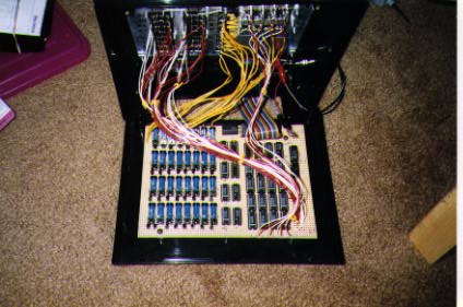
By the way, when I was in Junior High (around 1979?), I built a patch panel out of wood. I couldn't bring myself to throw it away, so here are two pictures of PatchBoy Version 0.
Sorry, I haven't drawn the schematic. If you're interested in the details, let me know, and that will encourage me to spend some time documenting the project better.
For the video switching I used a matrix of 32 five-volt SPST relays from Radio Shack (part 275-232). I have not had any problems with video bleed. -- Each relay has a small diode across the coil "backwards" to absorb voltage spikes when turning a relay off, and is driven by a very simple resistor-feeds-transistor circuit (I used common 2N2222 transistors).
For the audio switching, I used 4051 analog-switch chips. These are TTL compatible chips, and they are easy to use. (Jameco lists the part as 74HC4051...this appears to be the same as what I used.
The 4051 is a single 8-channel multiplexer. The 4052 and 4053 variants may be better for you if you only want 4 or 2 signal sources (dual 4-channel multiplexer, or triple 2-channel multiplexer).
These chips have a significant "on" resistance (about 60 ohms), but for line-level audio that seems to be no problem at all.
I tried to use these same chips to switch line-level *video*, but the results were not acceptable. For video switching I used reed relays instead.
I don't know a lot about interfacing on PCs (I used an Apple IIgs in my project), but if you have a parallel port that you can control, that would be very easy to interface to the 405x.
My Apple IIgs has an Applied Engineering I/O 32 card that provides 32 bits of input or output data. I'm using only 8 bits to control PatchBoy. The top bit is a strobe (briefly set high to cause PatchBoy to accept data from the other 7 bits). The next 3 bits choose one of eight four-bit latches (using a 74138 demultiplexer); the latches are 7475 chips. The designated latch takes a snapshot of the low four data bits when strobed.
Latches 0 to 3 correspond to the four pairs of audio outputs, and latches 4 to 7 correspond to the four video outputs.
The low three bits of each audio latch feed directly into a set of 4051 chips, and the fourth bit chooses between two banks of 4051s using the Enable inputs (each chip has 8 inputs, so it takes two banks to give PatchBoy 16 sets of audio inputs).
The video latches feed into 1-to-8 TTL demultiplexer chips (74138), and each output from a 74138 drives a resistor-transistor-relay assembly. Since there are only eight video inputs, the 4th bit of each video latch is ignored.
If you want to build something similar to PatchBoy, I recommend starting by building a small-scale project on a breadboard, to prove that it's going to work, and that it's going to work at a high enough quality for your needs. Specifically, hook up at least 2 sources of audio and 2 of video & make sure you don't get noticeable high-frequency bleed-through from non-selected sources.
If you collect the pin-outs for the 74138, 4051, and 7475, it's fairly straightforward to see how to hook them together:
Call the 8 data lines from the computer D0..D7. D7 enables the 74138 to decode 1 of 8 outputs. D6..D4 tell the 74138 which one; each of those 8 outputs goes to the latch ("clock"?) of a 7475. Each 7475 gets its 4 bits of input from D3..D0. Presto...eight separately-addressable groups of 4 bits, ready to feed to input-selection circuits, one per output.
I went with 8 sources for video, so out of each 4 bits I just ignored one, and used the other three to choose one relay out of 8 (with another 74138 per video output).
Getting 16 audio sources using 1-of-8 multiplexers means each channel (L/R) of each audio output needs two multiplexers. The latched-D3 bit chooses which of the two multiplexers is enabled (don't remember if I used separate inverters [7406], or if the 4051 had both "SELECT" and "NOT SELECT" inputs, saving the trouble). And the latched-D2..D0 tell both multiplexers which input to select (and the non-selected multiplexer ignores them).
| [ Home | Email ] | Last revised 28-Feb-2004 |